

Smooth closed-loop motor control depends on how well the drive settings match the motor, feedback device, and process response. A motor controller should not be configured only around rated power. Engineers also need to review motor data, feedback scaling, PID response, speed limits, and ramp times. When these settings work together, the system can respond to process changes with less hunting, overshoot, or unnecessary speed fluctuation.
Why Motor Data Matters First
Accurate motor parameters are the starting point for stable control. Rated voltage, current, frequency, speed, and power should match the motor nameplate. Incorrect values can affect torque calculation and current response, especially when the drive uses a more advanced control mode.
Motor identification or autotuning can also be useful when the controller supports it. For a vector control inverter, this process can help the drive establish a more suitable motor model and produce a more predictable response when load changes occur.
Load type should also be reviewed before PID tuning begins. Fans and centrifugal pumps behave differently from conveyors, mixers, or machines with higher starting torque. The controller settings should reflect how quickly the mechanical system can accelerate and how much inertia is present.
How Feedback Signals Affect PID Stability
PID control compares a target value with process feedback and changes motor speed to reduce the difference. Feedback may come from pressure, flow, temperature, or level transmitters. The input type must match the controller, such as 0–10 V or 4–20 mA.
Scaling should convert the electrical signal into practical process values. For example, a pressure transmitter should be displayed in the same pressure range used by the operator. Clear scaling makes commissioning easier and helps technicians identify unusual readings.
Signal direction also matters. If increasing motor speed raises the measured process value, the PID action must follow that relationship. Reversed logic can make the system move farther from the setpoint instead of correcting the error.
Where PID Gain Settings Need Attention
Proportional gain determines how strongly the controller reacts to the difference between the target and actual value. If the gain is too high, the system may react sharply and oscillate. If it is too low, correction can become slow.
Integral action removes remaining steady-state error, but excessive integral response can create repeated overshoot. Engineers should make gradual changes and observe the process after each adjustment rather than changing several values at the same time.
A vector control inverter can support tighter motor response when operating conditions require better torque or speed regulation. However, vector control does not replace PID tuning. Motor data, process feedback, speed limits, and gain settings still need to be coordinated.
Ramp Times Should Match Mechanical Response
Acceleration and deceleration times are often overlooked during PID setup. If speed changes faster than the process can react, the feedback value may lag behind the command. The PID loop may then continue increasing output and create overshoot.
Long ramp times can cause the opposite problem. The controller may respond too slowly when process demand changes. Suitable settings depend on load inertia, operating range, and how quickly the process should reach a new setpoint.
Minimum and maximum frequency settings are also useful. They prevent the drive from operating outside the practical range of the pump, fan, or other machine. These limits should reflect equipment requirements rather than replace correct PID tuning.
Protection Functions Also Influence Operation
Daily operation is more stable when control settings are supported by suitable protection logic. Overload, short-circuit, cooling, and motor temperature conditions can affect system response during abnormal operation.
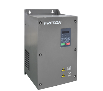
For this type of application, FRECON offers the FR380 Series High Performance vector control inverter. The series includes output-to-ground short-circuit protection, fan drive circuit protection, external 24 VDC short-circuit protection, and motor overload protection. Optional PT100 or PT1000 motor temperature protection is also available where temperature monitoring is required.
Fault response can be configured according to severity. Different faults can be set for early warning, fault shutdown, or continued operation. This helps technicians distinguish between conditions that need immediate stopping and those that should first trigger maintenance attention.
A Practical Commissioning Sequence
A useful commissioning process starts with motor data and rotation direction. Engineers can then confirm the selected control mode and verify that the feedback signal changes correctly when the real process value changes.
The next step is to set practical speed limits and conservative acceleration and deceleration times. After that, PID parameters can be adjusted under realistic load conditions. Testing at several operating points is more useful than checking only one setpoint.
FRECON can be considered when a project needs a drive that combines configurable control with multiple protection functions, but product selection should still follow actual motor and process requirements. A vfd with pid control will only operate steadily when the drive configuration matches the behavior of the system it controls.
What Defines a Smooth Configuration
There is no single PID value that works for every application. Stable operation comes from combining accurate motor parameters, correct feedback direction, practical signal scaling, moderate gain settings, suitable ramp times, and clear protection actions.
An ac motor controller should therefore be configured around the full process rather than one isolated setting. When electrical parameters, mechanical response, and feedback behavior are reviewed together, the system is easier to commission and less likely to suffer from repeated oscillation or slow correction during normal operation.
